Power Quality Meter

PM2218

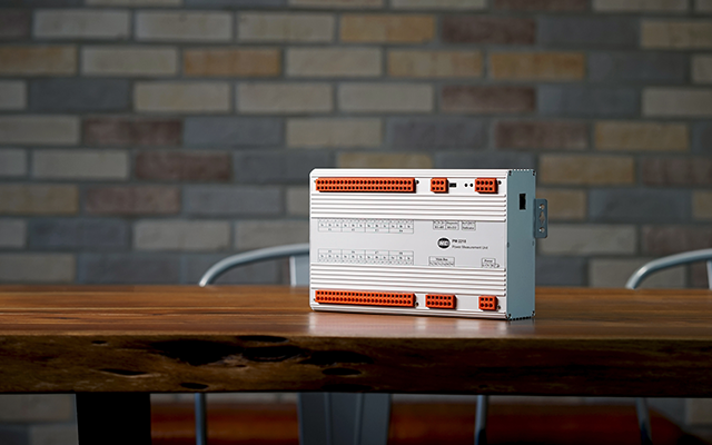
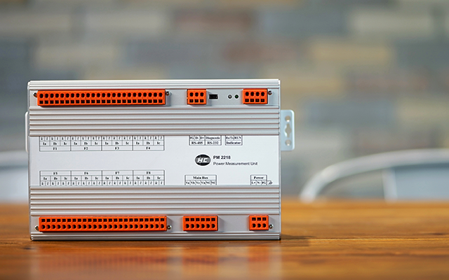
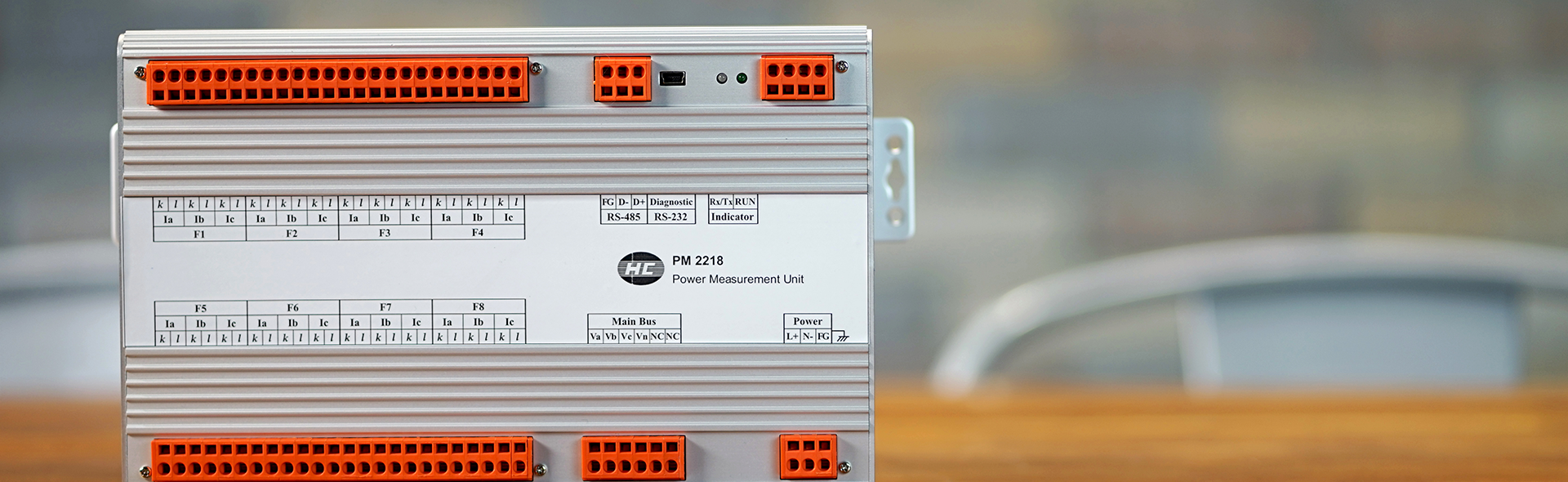
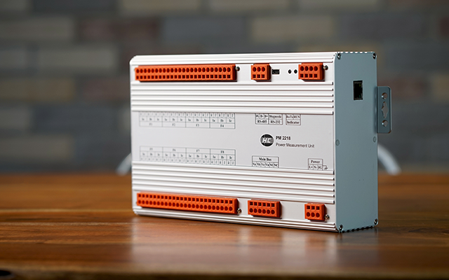
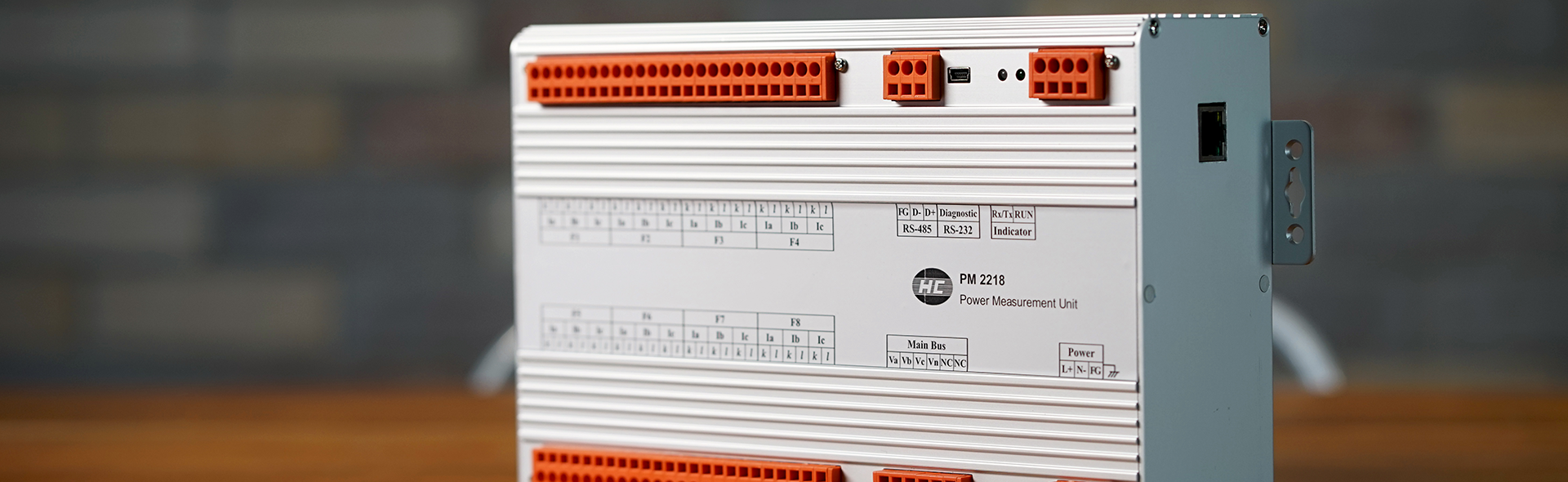
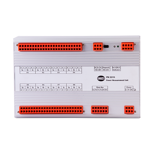
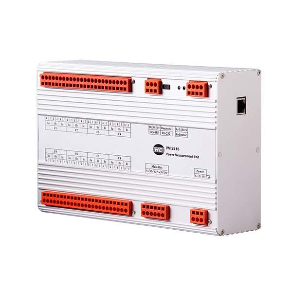
The design concept for Power Measurement Unit PM2214/18 is to provide accurate measurements up to 0.2% (for nominal frequency/voltage up to 0.05%) like 3-phase energy and power measurement with event logging, power quality analysis, flag and sag, and I/O capabilities to be the replacement of 4/8 feeder transducers.

The PM2214/18 is a great device for monitoring remotely of low/high power parameters in utilities/ industrial/ building/ factories automation and any of critical power enviroments. The PM2214/18 is not only the great cost saving device but also being great supportable to operations personnel take good care of power quality conditions and increase the equipment life and productivity


Provides accurate measurements up to 0.2% (for nominal frequency/voltage up to 0.05%) like 3-phase energy and power measurement with event logging, power quality analysis, flag and sag, and I/O capabilities to be the replacement of 4/8 feeder transducers.

Features

  • Power supervision / SCADA system
  • Feeder automation / customized
  • 0.05% high accuracy
  • Cost saving for 8 feeder transducers
  • Power quality analysis IEC 61000-4-30
  • Speedy real data conversion rate up to 1 cycle
     

Accuracy

  • 1. Unit configuration
    • 1-1 Processing and interface
      • CPU 32 bits
      • omports Main : RS-485 / option : LAN – RJ45
      • Diagnostic : RS-232
      • Protocol Modbus RTU
    • 1-2 Inputs Software setup Detection ( * vector composed)
      • Voltages / main bus 3U – 3 phase 4 wires Va, Vb, Vc, *V0 ;  *Vab, *Vbc, *Vca
      • 3U – 3 phase 3 wires *Va, *Vb, *Vc ;  Vab, Vbc, *Vca
      • Currents / 8 feeders 3I / Ia, Ib, Ic Ia, Ib, Ic, *I0 
      • 2I / Ia, Ic Ia, *Ib, Ic
      • Input setup and wiring 3P4W 3CT / 3U24I
      • 3P3W 3CT / 3U24I
      • 3P3W 2CT / 3U16I
      • Conversion 3 elements P, Q (P1, P2, P3, Q1, Q2, Q3)
      • ADC 16 bits with 16 synchronized channels
      • Rate of real data conversion, 1-32 cycle adjustable
    • 1-3 Power quality analysis (option) IEC 61000-4-30
      • Harmonic analysis
      • Voltage dips
      • Voltage unbalance (negative and zero sequence)
      • Voltage flicker △V10
      • Voltage low frequency spectrum (0.5-5Hz)
    • 1-4 Waveform recording (option) Ring buffer, length of 16 cycles total 1728 samples / three phase phasor
      • AC waveform 36 samples / cycle
      • Trend of speedy real rms datas 36 samples / cycle
      • 9 three phase phasors maximum
  • 2. Input ranges
    • Voltages Frequency : 45 – 65 Hz
    • 10 – 300V phase to neutral
    • Maximum over ≦1000Vrms, 2 seconds
    • Input resistance ≧1MΩ
    • Currents CT 5A ( 0 ~ 6A ) or CT 1A ( 0 ~ 1.2A )
    • Maximum over
    • 3 x CT continuous : ≦25 x CT, 2 seconds : ≦50 x CT, 1 seconds
    • Burden ≦0.1VA for 1 x CT input
  • 3. Measured parameters 
    • 3-1 Normal parameters 25±5℃
      • Stability
      • ≦ 50PPM (-10~50℃) , ≦ 70PPM (-30~70℃)
      • System frequency (Hz) ◎ 0.05% of nominal frequency
      • Voltage (RMS) ◎ 0.05% of nominal voltage
      • Voltages phase to neutral, phase and Σ
      • Voltages phase to phase, line and Σ
      • Current (RMS) ◎ 0.05% of nominal CT, Ia, Ib, Ic and Σ
      • Active power (W) ◎ 0.2% of (nominal voltage x CT), phase and Σ
      • Reactive power (Var) ◎ 0.2% of (nominal voltage x CT), phase and Σ
      • Active energy (WH) ◎ 0.2% of (Equate to Active Power), Σ each Feeder 
      • Reactive energy (VarH) ◎ 0.2% of (Equate to Reactive Power) , Σ each Feeder 
      • Power factor (PF) ◎ 0.2% (each phase and Feeder)
      • Phase angle ◎ 0.5° for A-V (each phase)
      • Phase rotation ◎ Auto-detection
    • 3-2 Power quality parameters
      • Sequence (voltage) ◎ 0.2% of nominal voltage
      • Positive sequence
      • Negative sequence
      • Zero sequence
      • Voltage unbalance ◎ 0.2% of positive sequence voltage
      • Zero sequence unbalance (%)
      • Negative sequence unbalance (%)
      • Distortion in harmonics Analysis in Va, Vb, Vc, Ia, Ib, Ic
      • Analysis with fundamental and 2nd to 17th
      • Distortion, HD-F and THD-F
      • Voltage flicker  △V10 (%)
      • Spectrum of low frequency  0.5 – 1 – 2 – 3 – 4 – 5 Hz
      • Voltage dips Pick up with time inversed curve
TOP