首頁
關於祥正
祥正簡介
祥正歷史
祥正產品
參考標準校驗電表
多功能電力品質表計
多功能電力品質轉換器
電力品質表計
電力配電管理
電力表計
電力傳訊器
電力轉換器
饋線終端單元
客戶端解決方案
最新消息
展覽訊息
服務與支援
祥正夥伴
聯絡我們
Search
Search
語言
ENGLISH
繁體中文
Espanol
返回目錄
電力品質表計
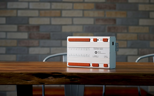
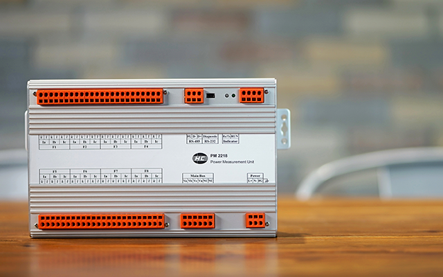
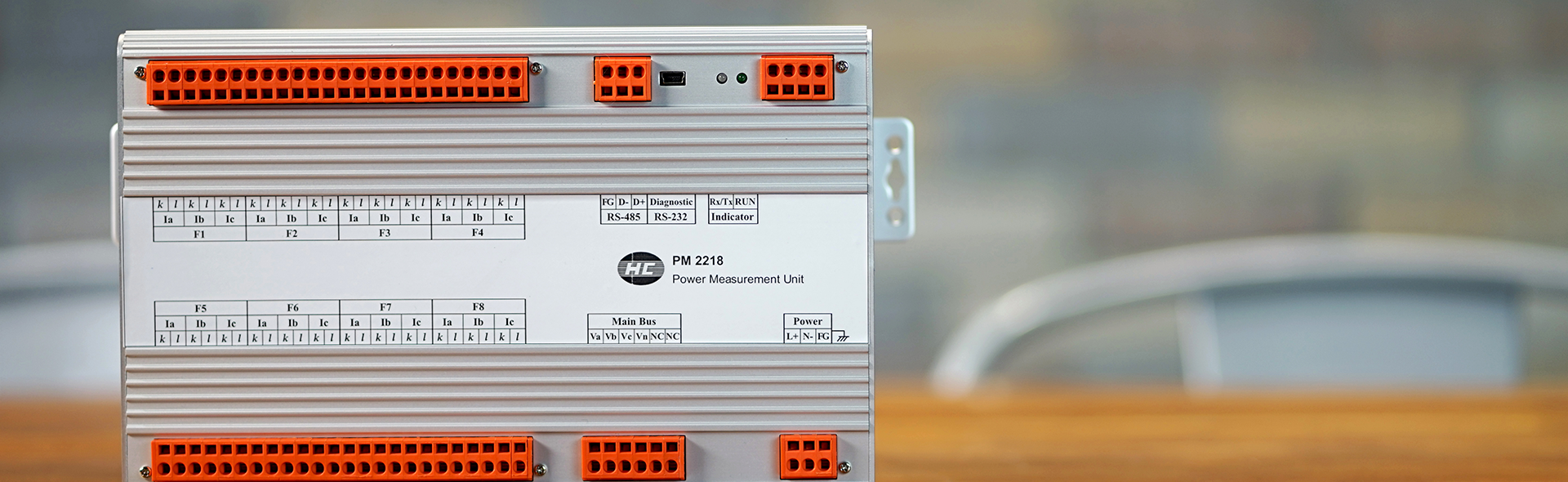
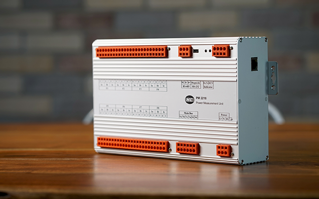
PM2218
下載
產品諮詢
產品說明
概述
產品特色
技術規格
電力測量單元PM2214 / 18的設計理念是提供高達0.2%的精確測量(標稱頻率/電壓高達0.05%),如三相電能和電力測量,具有事件記錄,電能品質分析,飄移和驟降, 和I / O功能可替代4/8組饋線轉換器。
PM2214 / 18是遠程監控公用事業/工業/建築/工廠自動化以及任何關鍵電能環境之下的低/高壓電力參數的理想元件。
PM2214 / 18不僅是一款節省成本的元件,而且對操作人員的幫助也很高,可以很好地監測電力品質狀況,提高設備壽命和生產率
提供高達0.2%的精確測量(標稱頻率/電壓高達0.05%),如三相電能和電力測量,具有事件記錄,電能品質分析,飄移和驟降, 和I / O功能可替代4/8組饋線轉換器。
特色
電力監視/SCADA系統
饋線自動化/客製化
精確度達到0.05%
用於8個饋線轉換器可節省成本
電力品質分析符合 IEC 61000-4-30標準
1個週期內快速即時執行數據轉換
Accuracy
1. Unit configuration
1-1 Processing and interface
CPU 32 bits
omports Main : RS-485 / option : LAN – RJ45
Diagnostic : RS-232
Protocol Modbus RTU
1-2 Inputs Software setup Detection ( * vector composed)
Voltages / main bus 3U – 3 phase 4 wires Va, Vb, Vc, *V0 ; *Vab, *Vbc, *Vca
3U – 3 phase 3 wires *Va, *Vb, *Vc ; Vab, Vbc, *Vca
Currents / 8 feeders 3I / Ia, Ib, Ic Ia, Ib, Ic, *I0
2I / Ia, Ic Ia, *Ib, Ic
Input setup and wiring 3P4W 3CT / 3U24I
3P3W 3CT / 3U24I
3P3W 2CT / 3U16I
Conversion 3 elements P, Q (P1, P2, P3, Q1, Q2, Q3)
ADC 16 bits with 16 synchronized channels
Rate of real data conversion, 1-32 cycle adjustable
1-3 Power quality analysis (option) IEC 61000-4-30
Harmonic analysis
Voltage dips
Voltage unbalance (negative and zero sequence)
Voltage flicker △V10
Voltage low frequency spectrum (0.5-5Hz)
1-4 Waveform recording (option) Ring buffer, length of 16 cycles total 1728 samples / three phase phasor
AC waveform 36 samples / cycle
Trend of speedy real rms datas 36 samples / cycle
9 three phase phasors maximum
2. Input ranges
Voltages Frequency : 45 – 65 Hz
10 – 300V phase to neutral
Maximum over ≦1000Vrms, 2 seconds
Input resistance ≧1MΩ
Currents CT 5A ( 0 ~ 6A ) or CT 1A ( 0 ~ 1.2A )
Maximum over
3 x CT continuous : ≦25 x CT, 2 seconds : ≦50 x CT, 1 seconds
Burden ≦0.1VA for 1 x CT input
3. Measured parameters
3-1 Normal parameters 25±5℃
Stability
≦ 50PPM (-10~50℃) , ≦ 70PPM (-30~70℃)
System frequency (Hz) ◎ 0.05% of nominal frequency
Voltage (RMS) ◎ 0.05% of nominal voltage
Voltages phase to neutral, phase and Σ
Voltages phase to phase, line and Σ
Current (RMS) ◎ 0.05% of nominal CT, Ia, Ib, Ic and Σ
Active power (W) ◎ 0.2% of (nominal voltage x CT), phase and Σ
Reactive power (Var) ◎ 0.2% of (nominal voltage x CT), phase and Σ
Active energy (WH) ◎ 0.2% of (Equate to Active Power), Σ each Feeder
Reactive energy (VarH) ◎ 0.2% of (Equate to Reactive Power) , Σ each Feeder
Power factor (PF) ◎ 0.2% (each phase and Feeder)
Phase angle ◎ 0.5° for A-V (each phase)
Phase rotation ◎ Auto-detection
3-2 Power quality parameters
Sequence (voltage) ◎ 0.2% of nominal voltage
Positive sequence
Negative sequence
Zero sequence
Voltage unbalance ◎ 0.2% of positive sequence voltage
Zero sequence unbalance (%)
Negative sequence unbalance (%)
Distortion in harmonics Analysis in Va, Vb, Vc, Ia, Ib, Ic
Analysis with fundamental and 2nd to 17th
Distortion, HD-F and THD-F
Voltage flicker △V10 (%)
Spectrum of low frequency 0.5 – 1 – 2 – 3 – 4 – 5 Hz
Voltage dips Pick up with time inversed curve
TOP